Although I’ve never been their biggest fan, this is nevertheless unwelcome news…


A LUCKY FIND!

So when I spotted this rare Lake Electronics PM-20 at last weekend’s radio rally, I quickly pounced on it and forked out a tenner to make it mine. It has two measurement ranges : 0-1000mW and 0-20W.
It seemed to be in mint condition and I couldn’t wait to get home to try it out. Sadly, things didn’t turn out too well, because it wasn’t working - at all 😓
I opened up the case to see if there was anything obviously wrong, but the inside looked even better than the outside, so I closed it back up and emailed one of Bolton Wireless Club’s members to seek help. Ross (G6GVI) very kindly offered to have a look at it during the next Club Meet.

At the Club, Ross explained where I should take some DVM readings and provided me with some additional guidance in the form of circuit diagrams. He also gave me a diode in case that was part of the problem.
Tonight, I reopened the case and briefly put a continuity meter across the PM-20 meter terminals to see if the coil was actually functioning and sure enough, the needle went full scale. Great! Before doing anything else, I decided to swap out the diode with the one Ross had supplied. I’m happy to report that the meter is now working!! 👌
I then spent some time adjusting the pots to get a readout which matched the indicated output of three QRP transceivers.

I’m really pleased to have this meter up and running and I thank Ross for his valuable help.
73 de Tom, M7MCQ.
PART 1 - THE BUILD

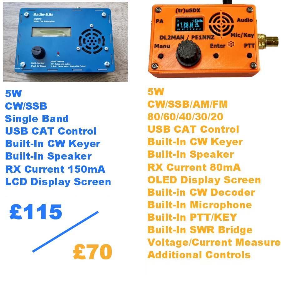
Size wise, the Explorer is bigger than I thought - it measures approximately 6" x 4" with a decent 2-line LCD screen just under 3" wide. There’s only a single control on the front panel which, from an ergonomics point of view, is less than ideal. It has a decent built-in speaker.
The kit cost me £115 plus postage. I guess the closest radio to this that I already own is the (tr)uSDX which is also available in kit form (£70) and is also a 5W CW/SSB Transceiver, but the big difference between them is that the (tr)uSDX is a 5-band radio while the Explorer is only single band. The 'orange wonder' also has quite a few extra useful features which are lacking on the Explorer.
Maybe the Explorer's receiver is a far better performer than the (tr)uSDX - I don't know yet, but we'll soon find out I guess.
The kit itself arrives in lots of sealed bags, separating components and keeping things organised. There are probably over 800 solder-joints to be made in this full kit, so that's a lot of soldering!! Thankfully, there is no SMD work.


Just like I did with the QDX KIT and the QCX KIT (amongst others) I will post on here throughout the build process, showing warts and all. If I mess something up, I will declare it and I will tell you how I got around it (or how it all ended right there). If it ends up in smoke, then so what? There'll be no tears. This isn't a $2 Billion space shuttle!
This post is PART ONE which will show the build. PART TWO will be a separate post covering the testing and performance of the kit (as built by a clueless beginner 😂 )
First job was to print off the manual and in particular the PCB LAYOUT page, so that each component can be marked off as it's soldered to the board. This is a really handy thing to do and it slows you down, which is always a good thing!!

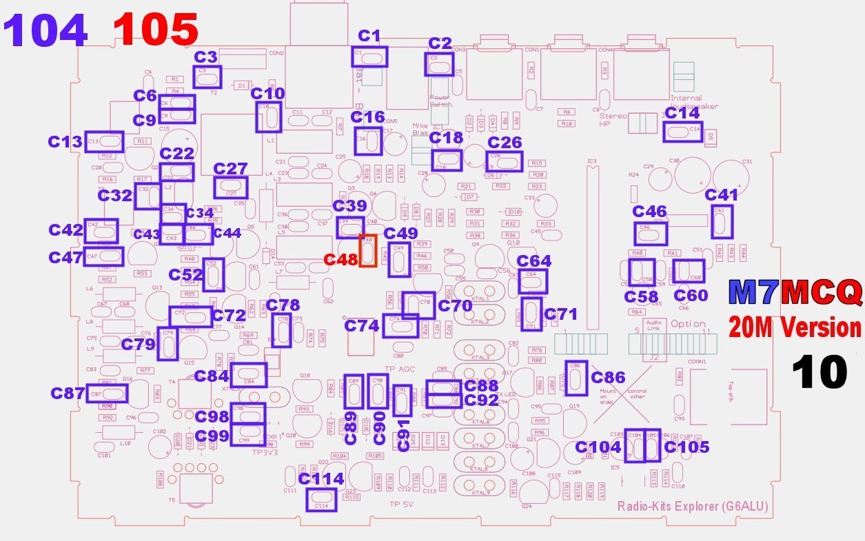
The first components to be installed are the ones from the bag marked "20M" and these include 1 resistor, 4 inductors, 11 capacitors and 8 crystals. None of these are polarised, so you can insert them any way around. My own pedantic nature forces me to insert the components in a particular way - eg all resistors are placed on the board in a manner that makes it easy to read their values - with the tolerance bands all to the right (or at the bottom if placed vertically). Having said that, I noticed later that I'd not fitted the yellow toroids all the same way 😡 I might desolder and turn it around😂
It very quickly becomes apparent that it can TAKE AGES to find things on the PCB because of how densely populated it is. Eg, I was searching for R93 for what seemed like forever. It wasn’t in an unusual place - I just couldn’t seem to see it! To help others quickly locate component locations, I’ve created some images (below) which will hopefully prove to be useful by showing you exactly where each component is located on the board to save you hunting around each time. I've grouped components together relevant to how they appear in the construction manual.


I strongly advise that you buy a PCB HOLDER like the one below to make life easier for yourself. Good lighting and a magnifier really helps too. And don't go cheap on the soldering iron - you'll need a good quality iron for this kit - one which can maintain 350+ degrees with a nice, fine chisel-tip. All these resistors are the miniature-type and much smaller than you may be used to.

Populating the board with all the resistors, capacitors and diodes is long and laborious, so it's important not to rush through - it'll just end up in tears further down the line. Checking for correct component value, correct placement and good solder joints every single time is crucial - the key to success.
Just a word of warning about the diodes - make sure you get the orientation right because one bank of diodes is oriented the same way, while other banks alternate. It's easy to get it wrong if you're not focusing.


 |
| Affix two pads |
 |
| Feed wires thru and pull gently from other side |
 |
| T4 & T5 completed! |


 |
| L1 and L5 need 15 turns, while L3 needs 16 turns |


The QRP-Labs QMX doesn’t have a lot of parts, but it is a tough little cookie - much more so than the Explorer. It’s not just a case of soldering a few bits and switching on - there’s a lot of tiny toroid winding, including some “Weird Twisted Sister” transformer work and then there’s the very tightly spaced components which make soldering a PITA (especially considering the larger ground plane).
The manual is pretty good, although it sometimes uses images which are similar to the QMX but not actually the QMX. At the end of the day, this kit is far from straightforward. There’s a lot to cram into a small space and it sometimes feels like an Airfix kit because of the modifications you have to make to standard components.
But before moving on, let’s all bow to the greatness of Hans Summers and his amazing design ideas. WOW! How the heck he comes up with these layouts I have no idea! It’s all very, very clever. But then when I try to squeeze the toroids into the tiny spaces around other components, I find myself saying “Would it hurt to have the PCB an extra 10mm wider”??
If I had to come up with a single tip for builders of this kit, I would say pay attention to the spaces around the toroids when placing the caps and diodes. If I was to build this thing again, I would have sat them just a fraction higher off the pcb so that I could manipulate them slightly to make a bit of room around the toroids. That way, you can move the enamelled wire around to get the best performance.
Apart from the fact that everything is squeezed in tightly, the kit was pretty straightforward to complete and there were no massive issues, so I won't bore you with step-by-step details, because the manual will provide all the help you need. Instead, I'll post photos of my build, showing views which I would have liked to have seen myself.
I have to admit that I am extremely pleased with myself for having successfully built this kit without a single error. I powered it up and after installing the FirmWare, it worked immediately, without a problem. I’d heard on the forums that many folk were experiencing problems and maybe it’s being aware of those problems that made me more cautious. Whatever it was, I feel quite proud of myself 😂
Here we go...


I'll post more when I get chance to use the QMX out in the field. Right now I don't have a resonant antenna with me and the swr is too high to operate on the one connected.
The good news is - it all seems to be functioning well on receive. More soon.
73, Tom, M7MCQ.
UPDATE (same day) - Just connected to a G5RV and used RBN to get a quick report on my CQ TEST M7MCQ transmissions…..
